
Prepared by Hamzah Djuned – Texas Tech Petroleum Engineer
DISCLAIMER – For educational purposes only
Aug 3, 2017, Jakarta Indonesia
General Scope of LNG Retail
The industry of natural gas continues to evolve including the use of LNG. The pricing of LNG throughout Asia as well as Europe is directly linked to oil. Throughout Asia, a rise in the demand for LNG has resulted in an influx of cargos to be diverted from other markets in order to satisfy the required need.
The changing industry and market has provided gas company with an opportunity to shift business focus and this could potentially benefit the consumer as well as the stability of gas company in general. The traditional use of natural gas in terms of heating, generation of power and industrial process’ have expanded further to include a larger portion of the transportation sector. Retail LNG will include a user interface unique to the market and will aid in the development of new infrastructures and these prices will be conditional to the direction of the market.
The evolution of the LNG market will influence an increase in demand and in addition to that this will also inspire existing consumers to expand their services into this particular field. As expected, the development of this new market will come hand in hand with challenges that will need to be overcome. It is extremely important to be knowledgeable over the properties and hazards of LNG products on top of the safety codes and standards which have been applied to the procedures within the gas company.
Basic Properties
Natural gas liquefies at a temperature of approximately -162°C or -259°F at atmospheric pressure. LNG allows the gas to take up a volume which is about 1/600th of its original size and this allows it to become easily stored as well as transported. The low temperatures which are associated with LNG classifies the substance as a cryogenic liquid and this involves special handling and technologies.
In order for the natural gas to remain a liquid, the LNG must be kept in a container with similar properties to a ‘thermos’. The cryogenic temperature of LNG gives the fluid the ability to freeze any type of tissue at the point of contact and causes other materials to lose their strength and functionality. This in result shows the importance of the choice in the materials used within the industry.
The general chemical composition of natural gas includes a mixture of mostly methane but as well as ethane, propane and butane with the addition of other hydrocarbons which are heavier. In addition to this, impurities such as nitrogen or hydrogen sulfide are extracted before the point of liquefaction. The boiling point of this liquid is able to define the moment at which the gas is able to transform into a liquid. The saturation dome provided graphically represents the relationship between pressure, temperature and volume of the substance.
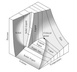
Saturation Dome
Further, the density of LNG depends slightly on the composition of the gas but in general it should sit at around 420 kg/m3 and 480 kg/m3 (3.5 lb./gal to 4 lb./gal). Specific gravity of the gas is relative to the density of the gas to the density of water ratio. The specific gravity of Methane at ambient temperature is about .554 and therefore this is lighter than air and this allows the gas to disperse easily in open areas. LNG in ambient conditions becomes a vapor and forms a cloud until it is able to diverge. At boiling point temperature and at atmospheric pressure the relative density of LNG is about 1.8 and in turn this results in the LNG vapors to be heavier than air and the gas will rest near the floor. As the Methane molecules begin to heat up and reach a temperature of about -110°C/-166°F, the relative density decreases below 1 and this allows the vapors to become more buoyant. At ambient temperatures, the specific gravity of natural gas is about .6 and this means that the natural gas vapors will rise.
The “Flammable Range” depicts the range of which the concentration of a certain gas or vapor is able to burn with the presence of an ignition source. These limits are referred to as the “Lower Flammable Limit” and the “Upper Flammable Limit” (LFL and UFL). LNG vapors are flammable if there is the presence of 5%-15% concentration of natural gas in the air.
Retail LNG Process
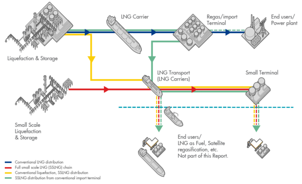
Traditional LNG process chain consists of multiple sequences as shown in the figure provided below. The natural gas is extracted from the wells under the phase of exploration and production. The natural gas is then turned into liquefied form at a liquefaction plant to aid with the transportation and storage of the hydrocarbons. Following this process the LNG is loaded on to tankers in order to transport the LNG to receiving terminals at which point it is regasified and distributed to consumers by pipelines or is transported abroad by road trailers in liquid form.
The production of LNG at a small-scale requires a different perspective than that compared to the conventional chain. As a result of developments in technology as well as economics, the small-scale LNG business chain has expanded from just a replica of world-scale LNG to a customization of small-scale LNG solutions. Small-scale LNG is considered a ‘value network’. Small-scale LNG can be sourced from either an existing conventional scale LNG or by a small-scale liquefaction facility itself. In addition to this, small-scale LNG serves a wider range of end users than that of a conventional value chain.
Equipment
The LNG retail value chain is an extension of the larger LNG trade which has been established for an extended period. This in turn translates to the fact that certain components utilized in the LNG service for the past decade can be repurposed for use in the retail LNG market.
Liquefaction Equipment
The basic processes over the distinct liquefaction technologies facilities on a global scale can be employed as the following:
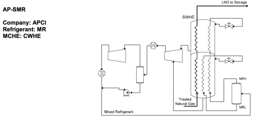
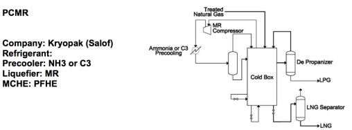
- Propane Pre-cooled, Mixed Refrigerant (C3MR): This serves as the most common large-scale liquefaction process of natural gas. C3MR is able to achieve a higher efficiency rate and capacity as compared to Single Mixed Refrigerant (SMR) because of the additional pre-cooling loop as well as the use of pure propane refrigerant and this is able to reduce the flowrate of the mixed refrigerant (MR) and debottleneck the compression system.
- Dual Mixed Refrigerant (DMR): Compared to the C3MR process, the DMR replaces the use of pure propane refrigerant for pre-cooling by implementing a second MR cycle which reduces footprint and propane stock. DMR is useful for floating liquefaction facilities.
- AP-X©: APCI’s process uses a nitrogen expander loop as a substitute for the MR which is used to sub-cool the LNG in C3MR or DMR. The reduction in the use of propane and MR flow rates leads to a higher production output with the omission of larger compressors and heat transfer equipment.
- Optimized Cascade©: This process was developed by Conoco-Phillips and uses a single component of refrigeration loops with the additional use of propane, ethylene and methane to successively cool and eventually liquefy the natural gas. This process requires the implementation of multiple small compressors and drivers to deliver the desired availability and flexibility.
On a smaller scale, there are a variety of simpler processes that have been successfully employed. These processes require less equipment than those used on a global export facilities and are far less complexed which lead to a simplified operation.
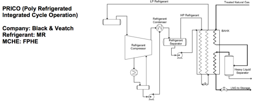
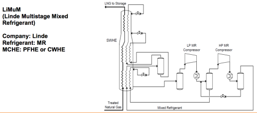
- Single Mixed Refrigerant (SMR): This process uses the application of a single closed-cycle loop in order to pre-cool, liquefy and sub-cool the natural gas. The primary exchanger is a plate-fin unit which is designed to offer a liquefaction system. The overall benefit of this process is the simplicity of the operation in addition to the reduced capital cost. The evolution of SMR process’ have reduced the amount of power required by modern plants to decrease by 25%-35%. SMR designs are available by several licensors.
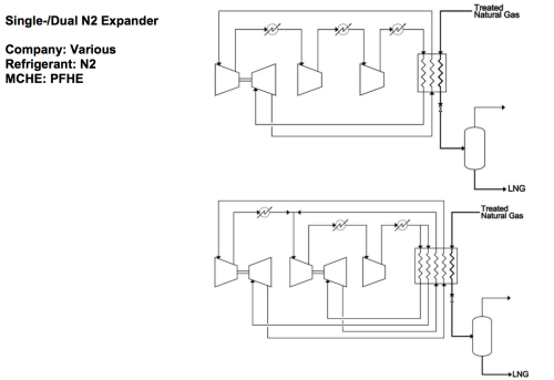
- N2 Expander: This process utilizes a reverse Brayton cycle in order to create refrigeration through the compression of nitrogen, removing the heat of the compression, and through the expansion of nitrogen through a turbo-expander to create a cool stream, then warming the stream by running it against the heat load. The N2 expander requires a lower capital cost but requires approximately 30% more power than the SMR cycle.
- Dual N2 Expander: This process utilizes nitrogen as the refrigerant similar to that of a single N2 expander. Two expanders or boosters are used, one for warmth and one for cooling, in addition to a single main heat exchanger to closely match the cooling curve of natural gas.
- Open Expander: 85% to 90% of the high-pressure gas stream is expanded and the remaining 10% to 15% is liquefied by using the cold energy which was produced. The low-pressure gas must be disposed of and this results in the placement of plants located nearby to consume the feed gas from the high-pressure main and tail gas delivered to the low pressure local distribution system.
- Sacrificial Nitrogen: In certain locations where liquefied nitrogen is found in abundance it may be commercially attractive to employ the use of sacrificial nitrogen. This process requires liquid nitrogen to be transferred using a heat exchanger. This heat exchanger receives the processed natural gas and the LNG is produced by the free cold which was emitted by the liquid nitrogen.
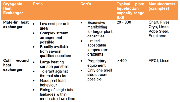
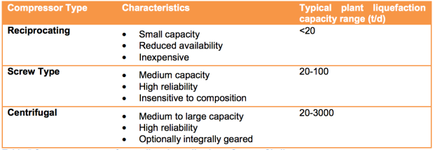
Further in addition to the differences over which thermodynamic cycle is used on the small-scale liquefaction facilities, alternative equipment may be employed to satisfy operational needs in terms of maintenance and reliability. For example, a reciprocating and screw type compressor may be preferred over the screw type compressor which is used in larger MR systems. In addition to that, drivers may be electric as opposed to the use of turbines and plate-fin heat exchanger can be used in favor of a coil wound exchanger.

Storage Equipment
Throughout the world-scale LNG process chain the application of different storage concepts are utilized. Some factors include storage volumes required by the market, local conditions, space which is available and permitting regulations. Storage tanks are generally divided into two sub categories, atmospheric and pressurized. The following designs are used at traditional LNG import and export terminals:
- Single Containment: Single containment tanks feature a primary liquid containment open-top inner tank, as well as a carbon steel primary vapor containing outer tank and an earthen impoundment berm for a secondary liquid containment.
- Double Containment: Double containment tanks are designed especially for the self-supporting containers, primary and secondary, and are also able to store liquids independently.
- Full Containment: Full containment tanks are designed with a primary liquid containment open-top inner tank with an outer concrete tank. The outer tank is implemented in order to contain the liquid and provide a controlled release of the vapors on the chance that a leak occurs.
- Cylindrical Full Containment Membrane: Membrane Containment tanks employ the use of a thin stainless steel corrugated membrane for the primary container. There is the presence of a pre-stressed concrete secondary container. Thermal insulators are present in the space in between the two containers.
- Non-Cylindrical Membrane: This membrane translates the technological benefits of prefabrication and modularization from the LNG shipping industry and can also maintain the same overall characteristics and performance of atmospheric storage.
- In-Ground Storage Tanks: These tanks were developed by Tokyo Gas Engineering and are used throughout Asia. These tanks are not required to be surrounded by a dyke or bund wall and this in turn comparably decreases the distance between the adjacent land and the tank.
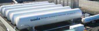
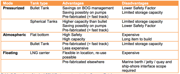
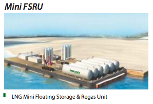
In terms of small-scale LNG, the typical capacity of storage ranges between 500 m3 to 5000 m3. There is the presence of a multitude of solutions towards storage and boil-off gas (BOG) issues and this in turn opens more possibilities to harness the BOG as opposed to liquefying or depressurizing it. Pressurized storage which are typically between 3-10 bars is usually found in small-scale LNG processes only. It is also important to recognize the increase in floating storage units (FSU) which may also be equipped with a regasification unit (FSRU).
- Pressurized
- Spherical Tanks: There are a very limited amount of onshore spherical tanks which have been reported.
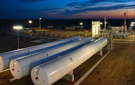
- Bullet Tanks: Unlike a conventional terminal, these class of tanks relieve the need to manage LNG boil-off gas by offering the capability to hold pressure during any given point in time. This storage tank is able to recondense the BOG within the receiving tank for long periods of time. Pressurized tanks have an average maximum capacity of around 1200 m3 but this volume will eventually increase because of near future developments. This tank is manufactured in factory and this results in saving time as well as money.
Pressurized Bullet Tanks
- Atmospheric
- Flat Bottom: Cylindrical atmospheric tanks are assembled on site and could take up to 2-4 years in order to be built up to a larger scale. These tanks are emptied from the top and the insulation performance of these particular tanks is exceptional. Unfortunately, these tanks do not have the capability to withstand the pressure needed to control a BOG management system at a size below 4000 m3, although it is possible for some of these tanks to be as small as 2000 m3.
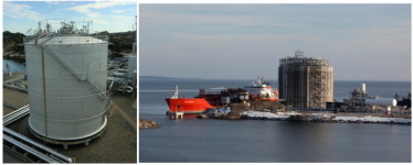
Atmospheric Flat Bottom Tanks
- Non-Cylindrical: The development of other small-scale LNG storage equipment in order to satisfy the need of the LNG shipping industry integrates the features of atmospheric tanks but at the same time retains a similar strength to a pressurized tank in terms of modularity as well as flexibility. These tanks have the capability to fill in the gap for volumes left between those which are too big for pressurized tanks and too small for cylindrical atmospheric tanks.
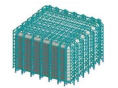
Atmospheric Non-Cylindrical Tank
- Floating Storage Unit
- A significant difference between small and large scale LNG carriers is the pressure which is allowable within the ship. Small-scale ships often use IMO pressure vessels or tanks of over 200,000 m3, in the other hand large ships use the capabilities of atmospheric tanks. An advantage provided by these tanks is that there is a limited amount of BOG and requires no management during the specified period. The BOG will be contained within the tank until the pressure and temperature rises to the designed relieving pressure. Unfortunately, a disadvantage about the use of this tank is the overall volumetric efficiency which is limited tank size and an increase in overall weight.
- Pressurized Storage: Main characteristics of LNG in this tank includes heat-in as well as the containment of BOG at an LNG temperature of about -126° with a density of 363 kg/m3.
- Atmospheric Storage: Main characteristics of LNG in this tank includes heat-out and the release of BOG at an LNG temperature of about -162° with a density of 423 kg/m3.
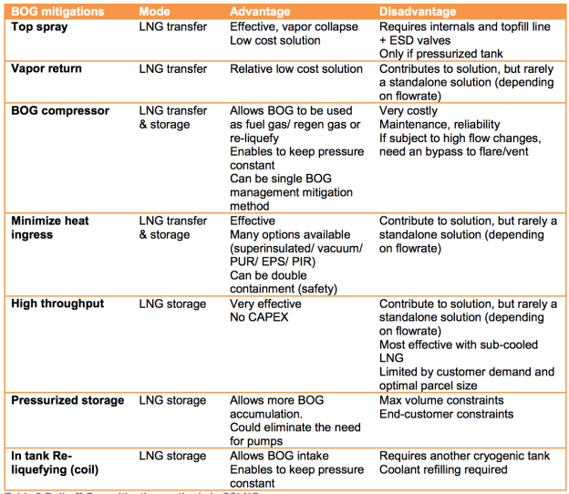
The emergence of the retail LNG chain has required an increase in the storage and transportation of small volumes of LNG. Throughout the completion of these process’, LNG is able to absorb heat from the atmosphere and increase the temperature within the piping and the equipment which is used, including the pumps. The rise in temperature of the LNG produces ‘boil-off gas’ (BOG) and this must be removed to allow the pressure within the storage tank to stabilize within operating limits. Pressurized storage has become the most common form to contain LNG because this enables the BOG to remain within the tank longer than compared to atmospheric tanks. The boiling point of the product increases and therefore the rate at which the BOG is generated is significantly reduced. Further, careful decisions must be made in the operations of transfer and storage in order to minimize the generation of BOG in order to omit the need for venting.
Transfer Equipment
The safe transfer of LNG from storage into transportation operations and back out to the consumer is essential to the scheme of LNG retail. The minimization of any spills is the most important concern which is associated within the transportation phase. LNG is transferred to vessels, trailers, rail cars and several other methods. The differential pressure between the storage and receiving vessel allows the use of cryogenic transfer pumps. These could either be submerged motor pumps or external pumps (ground pumps). The pumps are installed at the storage facility but may also be previously attached to the vessel or trailer involved in the transportation process.
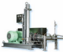
LNG Pumps
LNG Transfer (1250 L/min or 330 Gal/min)
- Gearbox Driven Pumps (GBS/CBS): This pump is mounted on the truck or grounded and is driven by a gearbox with a fixed speed motor.
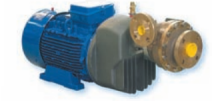
- Submerged Motor Pumps (VS): This pump is mounted externally on the ground or on the truck with a submerged motor.
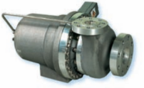
- Submerged Pumps (Sub Tran): This multi-stage submerged pump is mounted on the truck or grounded and is fitted into a sump and requires a frequency converter.
- Hydraulic Driven Pumps (CBSHD/CSH): This pump is mounted on a truck and is driven by a hydraulic motor.
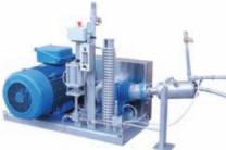
Mobile Pumping System
The following solutions have been developed for mobile tanker pumping units:
- Plugin: This centrifugal pump system for mobile tankers is powered through an onsite electrical network.
- Mixtran/Lextran: This autonomous centrifugal pump system for road tankers is powered through a generator coupled with truck engine PTO.
- Hytran: This autonomous centrifugal pump system for road tankers requires a hydraulic motor powered through the truck’s hydraulic system.
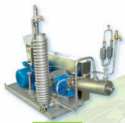
Stationary Pumping Systems
Reciprocating Pump for High Pressure LNG (600 bars or 8700 psi)
- SDPD: This reciprocating pump is used to slowly fill LCNG applications at a maximum rate of 250 Nm3/h.
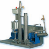
- MRP: This reciprocating pimp is usually used at LCNG refueling stations at a maximum rate of 870 Nm3/h.
- HPP: This oil lubricated reciprocating pump is used for larger LCNG refueling stations and natural gas peak shaving plants at a rate of up to 23,700 Nm3/h.
- LDPD: This reciprocating pump is applied for use at peak shaving plants at a maximum rate of 3000 Nm3/h.
- PD 3000: This vertical reciprocating pump is used for LCNG refueling stations at a maximum rate of 415 Nm3/h.
- GSV: This oil lubricated reciprocated pump is usually applied for use at large refueling stations with a maximum rate of 1,830 Nm3/h.
The marine infrastructure required for small-scale LNG will require less demands than compared to the installation of that for world-scale LNG. At the same time, the cost required to fulfill the needs are not to be underestimated. Transfer equipment required for small-scale LNG will occupy a significant area in order to consider safety procedures and precautions such as jetty length and truck plot space. Additionally, the transfer area includes gas and fire detectors, ESD panels and firefighting equipment. An interface is also implemented for the crew or truck driver, such as panels within a control room.
Refueling Station Equipment
Liquid to Compressed Natural Gas Refueling Stations
LCNG refueling stations have the ability to compress liquefied natural gas at a maximum pressure of 300 bars in order to fuel CNG appropriate vehicles. The advantages of an LCNG refueling station include but are not limited to those which are to be mentioned. The density of LNG at 1 bar is nearly 630 times more than that of CNG at ambient temperature. Further, LNG contains a much higher methane content than the gas which is supplied to the grid. The price of compression of LNG rather than CNG requires much less power. LCNG stations can also be established without the implementation of a gas pipe network. The overall cost of maintenance at an LCNG station is much less that that compared to an CNG station. Additionally, an LCNG station has the capability to be combined alongside an LNG station with the use of the same tank.
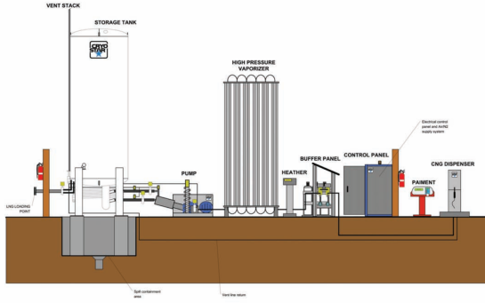
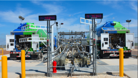
LCNG Refueling Station
LCNG Refueling Station Equipment
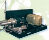
- High Pressure Pumps: A complete skid mounted pump and accessories allows for longer maintenance intervals as well as reduces gas loss. It is important to consider safety levels and efficiencies as well as installation costs.
High Pressure Pump
- Line Control Panel: A complete skid mounted panel would include vaporizer outlet temperature control, line and buffer pressure control, implementation of a valve to control buffer connection, automatic buffer isolation and a connection for odorizer entry. It is important to consider safety precautions and therefore the implementation of a main line shut-off valve for shut-down safety procedure is essential. The panel should also include line and buffer pressure indicators and valves.
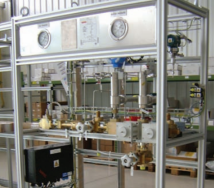
Line Control Panel
- Programmable Logic Controller (PLC) Panel and Software: It is essential for the PLC panel and software to have a friendly user interface in order to ensure proper operation. This panel and software is able to control the whole LCNG station with the application of proper station management software. Some panels and software offer access to remote maintenance. It is essential for the panel and software to offer fully integrated safety features.
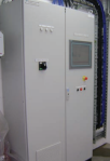
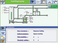
Programmable Logic Controller Panel and Software
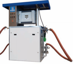
Liquid Natural Gas Refueling Stations
LNG refueling systems require the use of LNG or liquid biogas storage tank and has the capability to refuel liquefied natural gas at pressures of up to 20 bars. The advantages of LNG stations include but are not limited to those which are mentioned. Overall reduction of the on-board vehicle tank size through the decrease in weight as compared to CNG, increased in vehicle autonomy, the ability to recover the vehicle boil-off gas and a much lower investment cost per kg of dispensed gas. In addition to that, the refueling time is relatively short and there is a very high refueling measurement accuracy. The pump is able to instantly start and stop as well. This type of refueling stations is available for both single and dual nozzle vehicles (otherwise referred to as cold and saturated). This refueling station also provides the capability of managing the pressure within the storage tank. This also provides the possibility to integrate saturation as well as unloading functions to the pump skid.
LNG Refueling Station
LNG Refueling Station Equipment
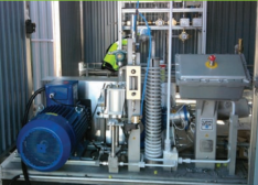
- Multifunction Submerged LNG Pump Skid: The LNG pump skid has the capabilities to flow with a capacity of 320 L/min in addition to an instant start and stop of fueling through the application of a submerged Sub Tran pump. The plug and play design allows this pump to connect to the storage tank as well as the dispensers. This pump may also feed into two dispensers. The gas loss associated with this component is quite low. The system is able to maintain a constant flow and refueling pressure. This equipment is available or otherwise compatible with saturation and trailer unloading functions.
Multifunction Submerged LNG Pump Skid
- LNG Dispenser Coriolis Flow Meter: The LNG Dispenser Coriolis has the capability to flow at 160 L/min at the nozzle and is also able to fuel cold and saturated vehicles. These usually have high measurement accuracy and are fully equipped with hoses, nozzles and a break away system. The nozzle is provided with a heated receptacle and some are available with a back-vent nozzle. Additionally, this meter is able to automatically recover vehicle boil-off gases.
LNG Dispenser Coriolis Flow Meter
- Programmable Logic Controller (PLC) Panel and Software: It is essential for the PLC panel and software to have a friendly user interface in order to ensure proper operation. This panel and software is able to control the whole LNG station with the application of proper station management software. Some panels and software offer access to remote maintenance. It is essential for the panel and software to offer fully integrated safety features.


Programmable Logic Controller Panel and Software
Transportation Equipment
- Marine Transportation: The utilization of an LNG barge or a small LNG carrier is the main approach towards marine transportation of LNG. It is expected that a small-scale LNG barge and carrier are to meet the same regulations, designs and standards as compared to world-scale LNG shipping. The marine transfer of LNG has an excellent record in safety and over 75,000 shipments have been made from export terminals to onshore and offshore receiving terminals around the world. LNG vessels must follow the requirements provided by the International Maritime Organization (IMO) and the International Gas Carriers Code (IGC) in addition to any requirements imposed by the government of registry.
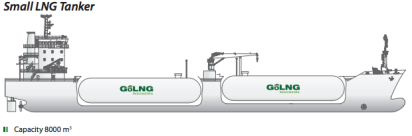
Marine Transportation (8000 m3)
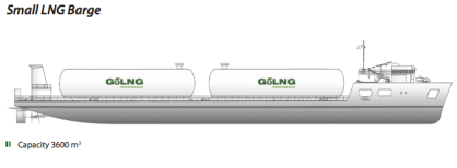
Marine Transportation (3600 m3)
- Overland Transportation: The utilizations of Road, ISO or Rail Trailer is perhaps the most common method of overland transportation in the LNG retail chain. The Road Trailer is the most commonly used transportation means overland and has been used specifically to refill storage tanks at refueling stations in addition to directly refueling marine users at ports. Inter-modal Transportation via Iso-Containers is also a possibility and option which is used to transport LNG between a road trailer, rail and container ship and this provides flexibility in terms of transportation. This transportation is highly considered for remote island users. LNG road trailers also have an extensive and highly impressive safety record in operation. The implementation of ‘active’ systems allow us to monitor the vehicle conditions such as speed and turning radius and this allows us to develop calculations in terms of breaking and etc. Cryogenic trailers continue to decrease in weight and increase in containment capacity. Insulation technologies continue to improve and thus provides an improvement in performance and flexibility. It is essential to understand the differences in the insulation designs of these trailers.
Road Transportation
- Cryogenic ISO Containers: Cryogenic Iso containers have been optimized in order to transport LNG worldwide by rail, sea or road. These containers also have the ability to be used as on-site storage and these vacuum insulated ISO containers are designed for thermal performance and simple operations as well as safety procedures. ISO tunnels are implemented for chassis applications and can be enhanced with pressure build circuits which allow them to be utilized within the LNG vaporization phase.
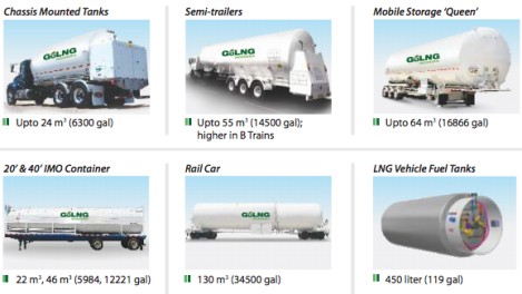
Transport Tanks
Regasification Equipment
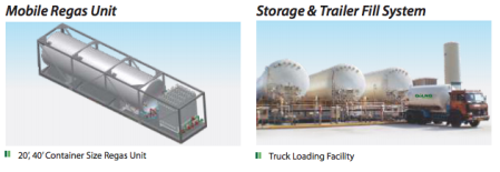
The development of large regasification/import terminals occurred in order to reduce the total cost of massive LNG vaporization. Simpler processes as well as technologies have been employed which are similar to the design of those used by the industrial gas industry, for example, air vaporizers.
The installations of small-scale LNG are usually unmanned and in the off chance that it may require assistance the personnel are minimized and used only for maintenance as well as unloading. Conventional terminals may often have the presence of 200 people. Regasification plants are built with equipment which is prefabricated and pre-assembled prior to being transported on site. This provides a faster project schedule, especially in terms of the tank. The use of pressure build up within the tank before the point of regasification is also practiced in some cases instead of a pump.
Without compromising the overall safety of the plant, measures which are taken during small-scale LNG are simpler compared to world-scale LNG. In addition to this the maintenance required is reduced because there are less rotating parts and instruments which are used throughout the process.
A flexible hose with a dry break coupling used as the emergency disconnection system (EDS) can be used in order to transfer the LNG. The boil-off gas, which is produced from the generation of LNG, is handled within the pressurized tank, until the point where it is condensed with the next subcooled LNG or by the liquid nitrogen provided by the backup.
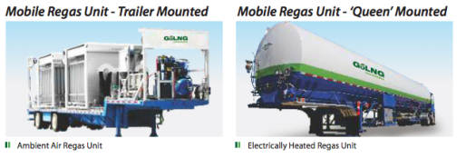
Further, the use of air vaporizers is preferred in small-scale LNG because of the simplicity that the equipment was designed with and the absence of operating expenditures. These vaporizers are installed redundantly to allow some vaporizers to defrost while others are operating.
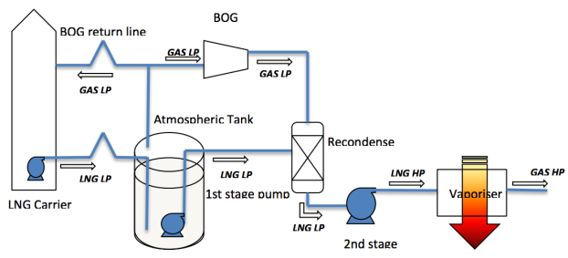
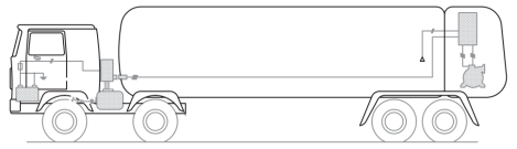
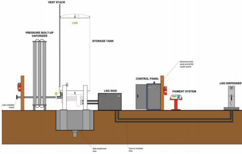
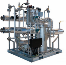
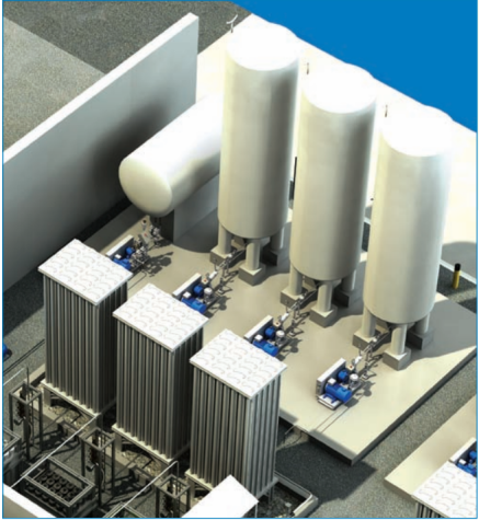
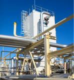
Typical Conventional Regasification
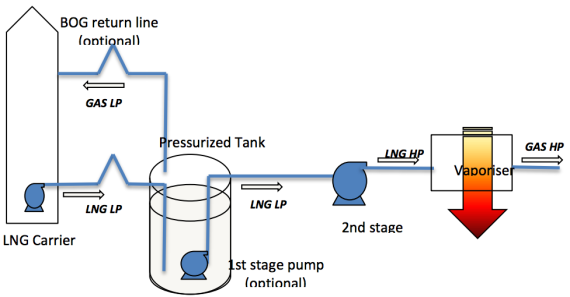
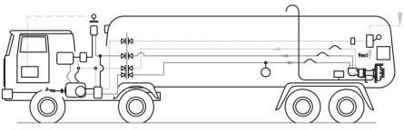
Typical Small-Scale Regasification
Conventional LNG receiving terminals have been built along the coasts or near large bodies of water and the use of seawater is applied as the heating source for vaporizing and heating the LNG into ambient temperature gas. The development of new LNG receiving terminals have surfaced and are as follows.
- Floating Storage Regasification Units (FSRU): These particular receiving terminals have undergone modification in order to become compatible with vaporizers/regasifying equipment. The use of LNG vessels in order to accommodate this equipment eliminates the need of certain civil engineering designs as well as the construction of LNG tanks which are required for land terminals. An additional advantage of an FSRU is the mobility which allows it to be used in other locations as well. Additionally, damage and mishap to general population can be easily avoidable but measures must be taken against the pitching and the rolling of the hull.
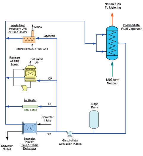
- LNG vaporizer systems with air heat-source: The heat source used to vaporize and warm the LNG is generally seawater in this primary receiving terminal. The use of seawater requires investments in order to consider the intake as well as the discharge of water. Environmental regulations must be considered for cold seawater after the heat exchange with LNG. In addition to this, the development of non-seawater based vaporizer system was developed to vaporize the LNG using a reasonable temperature produced by a glycol solution. The glycol is heated by using the heat from the air released by a fan and reused for the vaporization process. This vaporization system is only applicable to areas with atmospheric temperature of 15°C or higher.
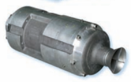
- Open Rack Vaporizers (ORV): Within an ORV, the LNG flows through the heat exchanger tube and is able to exchange the heat with the seawater which flows on the outside of the heat transfer tube in order to gasify the LNG. This occurs as the LNG flows through the inlet nozzle and passes through the manifold and a header pipe in order to be sent through a set of panels which each consist of an array of heat transfer tubes.
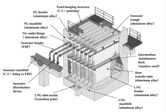
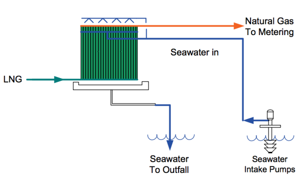
Open Rack Vaporizers
- SUPERORV: During the operation of ORV, the outer wall temperature of each heat transfer tube sinks below the freezing point of seawater and this causes ice to form on the tubing. Depending on the temperature of the seawater, the thickness and the height of the ice varies significantly and this results in resistance to the heat transfer process. Thus, ‘Kobe Steel’, has developed a heat transferred tube known as SUPERORV which includes a duplex pipe structure. The lower part is used to suppress the icing on the outer surface of the heat transfer tube and this has greatly improved the vaporizing phase in the LNG process.
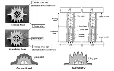
SUPERORV
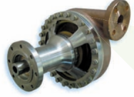
- Intermediate Fluid Vaporizers (IFV): In the IFV process, saltwater is used in order to vaporize LNG by using a heating medium such as propane. The structure of an IFV combines three types of shell-and-tube heat exchangers, an intermediate fluid vaporizer, LNG vaporizer and an NG trim heater. LNG flows through the heat transfer tube and following this the LNG exchanges heat with the intermediate fluid gas above the shell, by this point is almost entirely vaporized as it is transferred to the shell side. The LNG then exchanges heat with saltwater that flows on the inside of the heat transfer tube and is warmed up to be delivered as gas at ambient temperature. As a result of the heat exchange, the intermediate fluid is condensed on the outer surface of the heat transfer tube and drops down to the shell to exchange heat with the seawater which is flowing through another set of heat transfer tubes. The fluid is then vaporized again as the intermediate fluid, usually propane, is flowing through the LNG vaporizer.
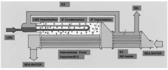
Intermediate Fluid Vaporizers
- Submerged Combustion Vaporizers (SCV): The structure of an SCV utilizes an underwater burner which burns fuel-gas in order to generate heat which vaporizes the LNG. This system consists of a tank, an underwater burner, a bundle of heat transfer tubes, combustion-air fan and a device to control fuel-supply. The heat transfer tubes and the underwater burner, the exchanging portion as well as the heat source, are submerged and the water is heated. The high temperature results in the combustion gas to be released by exhaust into the water. The exhausted gas forms a two-layer flow of mixed bubbles and this further helps promote a more effective heat exchange. The use of combustion gas as the heat source gives the vaporizer the ability to be significantly smaller than other vaporizers which can hold the same capacity. Even when the fuel gas suddenly stops the supply of vaporizer gas will continue for a limited time because of the capacity of the heated water bath. SCV does not require an intake facility for water and overall reduces the construction cost. Unfortunately, the running cost is very high because 1.5% of the vaporized LNG must be consumed as fuel.
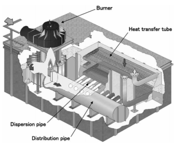
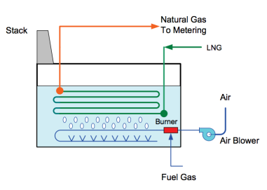
Submerged Combustion Vaporizers
- Ambient Air Vaporizers (AAV): Direct ambient air vaporizers are used throughout the cryogenic services and most significantly within the air separation plants. AAV’s are vertical heat exchangers which are designed to defrost the accumulation of ice on the tubing. Automatic shipping valves are installed to allow automatic defrosting with the implementation of timers. In comparison to other vaporizer options these require more vaporizer units and occupy more overall space. AAV utilize direct contact, with long, vertical heat exchange tubes that are able to influence a downward airflow as a result of differential densities. The performance of AAV’s are solely based from the inlet and outlet conditions as well as site and environmental factors. This vaporizer system is especially effective in hot climates along the equator where the ambient temperature is high throughout the year.
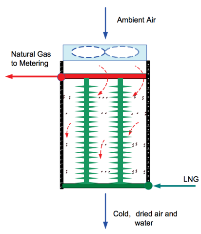
Ambient Air Vaporizers
Peak Shaving Systems
The purpose of peak shaving systems or plants allows the storing and supplementation of natural gas on the basis of demand in the case that there is an unexpected increase in the consumption of gas or if there is a lack of supply from the natural gas grid. These systems often require the utilization of very high flow rates and a range of pressures. Following the pressurization of the LNG, it is sent to the vaporizers and injected back into the grid. This system consists of LNG storage tanks, high pressure pumps, regasification equipment and a regulatory system which is managed by the plant control system that can often be accessed remotely.
There are two types of peak shaving systems and both include the utilization of on-site LNG storage while the other includes on-site liquefaction capabilities. This particular peak shaving facility is capable of liquefying and storing natural gas directly from the pipeline. On the other hand, without the liquefaction facility the peak shaving system must depend on LNG tankers to refuel the storage tanks.
Peak Shaving Plant
Case Study
George West, Texas
- Highlights:
- Liquefaction of pipeline gas which provides fuel for high-horsepower engines used in the oilfields and in the regional transportation as well as industrial sectors.
- Strategic location within the Eagle Ford Shale
- March 2015
- Significant Accomplishments:
- Implementation of two truck loading racks which have the capabilities to load two transport trailers simultaneously within one hour.
- Completion of an integrated control system which allows for remote monitoring of LNG production, storage and flow on site.
- Efficient energy turndown and restart capabilities upon production which allows for market flexibility.
- Incorporation of second production train in the case of future expansion.
- Application:
- LNG production facility open 24/7 throughout the year. Providing LNG as an alternative fuel to diesel for high-horsepower engines which operate in the oilfield; this plant also offers high quality LNG for local merchant use.
- Pleat Features:
- Chart C100N standard LNG Plant
- Natural gas liquefaction capacity of 100,000 gallons per day (165 tons per day)
- Includes proprietary nitrogen cycle process technology, pre-treatment, plate-fin heat exchangers, cold box, air cooled heat exchangers, storage tanks and load out facility.
- Standardized ‘off-the-shelf’ designs built at U.S Chart manufacturing facilities.
- Maximized shop fabrication and minimal field construction.
- Simple plant operation.
Small-Scale LNG Liquefaction
Vendors
Chart

- Chart is the world’s leading single-source LNG equipment and solutions provider across the complete LNG value chain in terms of liquefaction, distribution, storage and end-use fueling.
- Liquefaction: Chart standard and modular liquefaction plants and associated process technology enable the displacement of liquid fuels through small and mid-scale LNG.
- Distribution: Liquefied natural gas can be transported by road, rail or sea and Chart offers a complete portfolio of super vacuum insulated solutions to make these distribution opportunities possible.
- Storage: Chart provides complete storage and regasification solutions providing natural gas at the point of use per customer capacity and withdrawal requirements.
GoLNG Indonesia

- GoLNG Indonesia has designed small LNG Tankers and LNG self-propelled barges that consider the topography and the different operational challenges that can be found throughout Indonesia. GoLNG can provide a fully internal management of LNG shipping solutions to their customers.
INOXCVA India

- INOXCVA is a global cryogenic major company offering complete cryogenic liquid and gas transportation, storage and distribution solutions to the industrial gas, oil field as well as LNG industry.
Cryostar

- Cryostar is able to offer a range of small-scale LNG plants for on- shore natural gas or biogas liquefaction application. Cryostar has experience with boil-off gas re-liquefaction system on-board LNG carrier.
- Cryostar has the capabilities to supply customers with a complete supply chain solution from natural gas to end user including LNG trailer loading stations and LCNG/LNG refueling stations.
- The bulk of Cryostar technology is based off a closed refrigerant cycle to produce the cooling source which is needed to condense the natural gas.
Works Cited
Demoury, Vincent , comp. Retail LNG Handbook. Vol. 1. N.p.: GIIGNL, 2015. Groupe International des Importateurs de Gaz naturel Liquéfié. Mar. 2015. Web. 1 Aug. 2017. .
Egashira, Shinji. LNG Vaporizer for LNG Re-gasification Termina. Tech. Kobelco Technology, Dec. 2013. Web. 1 Aug. 2017. .
“LNG Systems.” INOX India Pvt. Ltd.N.p., n.d. Web. 01 Aug. 2017. .
Patel, Dhirav . LNG Vaporizer Selection Based on Site Ambient Conditions. Tech. Ed. John Mak, Daniel Rivera, and Joanne Angtuaco. Gas Technology , n.d. Web. 1 Aug. 2017. .
Cryostar . Small Scale Liquefaction & Distribution Biomethane and Natural Gas. N.p.: Cryostar , n.d. Cryostar. Web. 1 Aug. 2017. .
Small Scale LNG. Rep. N.p.: n.p., n.d. International Gas Union. World Gas Conference, June 2015. Web. Aug. 2017. .
GoLNG Indonesia. Small Scale LNG, LNG Supply Chain ‘End to End Solutions’. Jakarta: GoLNG Indonesia, n.d. GoLNG Indonesia. Web. 1 Aug. 2017. .
Small-Scale LNG Liquefaction. Issue brief no. 6. Chart Inc., 2016. Web. 1 Aug. 2017. .

I have 5 year experience in electrical
DAE .electrical passed by A+ and b.texh pass continue
I have electrical supervisor licence from govt of singh
currently job holder in aisha shteel
mi port qasim Karachi
LikeLike
I would like to apply for the post of liquefied natural gas in your company .Hence forth ,please find the resume attachment with mail.Avidly looking for positive response towards the concern
LikeLike
10th pass driving license long gulf returns no 8003958861
LikeLike
Neetu Singh mca indian gas agency
LikeLike
I am diploma civil engineer
LikeLike
Sir I am Tig @Arc Welder eny vacancy this company
LikeLike
Hello; Sir., let me know job available, I’m sailor and oil/chemical tanker. hijack2015.hj@gmail.com
LikeLike
Dear sir I should be also join your company because my qulification 3year diploma chemical engineering (Petro chemical) from GTI (Govt technical institute)
LikeLike
Sir I’m need job so u accepte me
LikeLike
I am a Brooker to a Direct Mandate working with a reputable refinery,
and we are please to inform you esteem buyers that the petroleum
products you are looking for is available in our Tanks and reservoir
for immedaite lift and supply.
SUCH AS
1) JP54
2) JPA1
3) MAZUT
4) AGO
5) LNG
6) LPG
7) D2
8) D6
9) REBCO
10)EN590
Please contact us via our official email address.
nikolayviktorovichk61@mail.ru
Thanks.
Nikolay Viktorovich Kozlov
LikeLike
Hi Im Gulam Waris …CNC Operator in TATA MOTORS LTD…….and CNC Programmer in HERO MOTO CORP .in INDIA
LikeLike
I am Md Nipu Hossain from Bangladesh, i want to a work permit visa .please help me and mail me. nipudoer@gmail.com
LikeLike
I am a Brocker to a Direct Mandate working with a reputable refinery, and we are you to please inform us esteem buyers that the petroleum products you are looking for is available in our Tanks and Reservoir for immediate lift and supply.
SUCH AS
1) JP54
2) JPA1
3) MAZUT
4) AGO
5) LNG
6) LPG
7) D2
8) D6
9) REBCO
10) EN590
Please contact us via our official email address phone number.
ivanartur26@mail.ru
+79260025997
Thanks.
Ivan Artur Zhestokov
LikeLike